ASICs in Electronic Instrumentation
H. Leopold, W. Meusburger, R. Röhrer, H. Senn, P. Söser
Institut für Elektronik, Technische Universität Graz
A-8010 Graz, Austria
Application Specific Integrated Circuits (ASICs) are used for various reasons in electronic instrumentation. The most significant advantages in industrial environment are obviously less power consumption and less space combined with a good possibility of signal conditioning for proper information transfer to a central processing unit. In laboratory equipment reliability and flexibility as well as the reduction of cost and space are the counting arguments for the use of ASICs. This paper will give a review on projects already worked out at the Department of Electronics and will then — as the annual report of UNICHIP Graz — focus on an ASIC devoted to highly accurate thermometric instrumentation.
Introduction
The Department of Electronics at the Technical University Graz started to design integrated circuits (IC) in 1988. Since then several systems have been developed in the department comprising ASICs devoted to electronic instrumentation. The methodology involved spans from gate-array to standard-cells if digital; in case of analog or mixed-mode the analog section is full-custom.
The systems under consideration are predominantly sensoric sensing physical properties of liquids (density, velocity of sound, and temperature) either in the harsh environment of industrial process control or in the clean laboratory with the highest level of accuracy.
Instrumentation in Industrial Environment
There are various reasons for the use of ASICs in electronic instruments for industrial environment. Our systems being in almost all cases instrumentation designed to support sensors the small size of the ASIC is very much appreciated as such systems fit directly into the probes. The small outline helps with respect to electromagnetic interference and to mechanical robustness. If power consumption is low the system can be supplied with a current loop (typically 4 – 20 mA), which is also used to carry information to the central processing unit. Both requirements (small, low power consumption) can be met with ASICs. Three ASICs of this kind have been developed at the department in the last years. They are briefly described in the following chapters.
GOETHE
This was the very first gate-array design [1] in the field of industrial instrumentation at our department. It was thought to replace a PCB system which was used to encode the temperature of a liquid into a bit-stream locked in frequency to the periodic signal coming from a mechanical oscillator carrying information on the density of said liquid. In other words, the temperature was measured using a platinum thermometer and a reference resistor in an integrating ratiometric Analog-to-Digital Converter (ADC). As the clock for the ADC was the mechanical oscillator, the resolution in temperature with respect to time was by far to low.
The ASIC (GOETHE) had an on-chip crystal oscillator to provide a fast clock signal for the ADCs. The control- and the quantization units for two of them were integrated in the gate-array. The resolution is 20 bit each. The analog sections of these ADCs are added off-chip. The results of the conversions are counted BCD numbers. They modulated the pulse width of the mechanical oscillator signal. The information was transferred by means of a binary current signal on a two-wire line also providing the power for the whole sensor system.
This ASIC brought the expected increase in performance and a significant decrease in space needed for the interface system.
ASTERIX
This ASIC was the first standard cell design at our department. It is used in a warm water boiler to periodically "wake up" a microcontroller which then takes measurements of temperatures and performs calculations on whether there is enough energy stored or not. The results are sent back to the ASIC which offers a multiplexed LCD driver circuit. The display shows status information.
The main advantage of this ASIC was an enormous reduction in the power needed to operate the control system as only a very small part was active all the time and the power consuming parts were activated for just a short period. With the multiplexed LCD driver in the ASIC a reduction of the package to a 28 pin type could be achieved. This saves extra cost for the PCB and the ASIC.
The development of ASTERIX was a cooperation of an Austrian enterprise, Joanneum Research and our department. ASTERIX is part of a product of this Austrian enterprise.
SUPERGOETHE
This ASIC is a more powerful version of GOETHE. Therefore a standard-cell approach was chosen in a 1.0 µm CMOS technology [2], [3]. The system was extended to be able to operate the analog sections of three 20-bit ADCs and to quantize up to three periodic signals (both density and velocity of sound are transferred to periodic electrical signals; the information is the length of the period) with selectable resolution. The problem with this quantization is the absolute accuracy, the long time- and the temperature stability of the crystal oscillator in the interface. To avoid this problem a method of counting multiple periods with no error and determining the length of these periods by counting a high frequency oscillator clock is used. If the rate for the information transfer and the oscillator clock have a fixed ratio the clock period can be measured in the central processing unit, where power consumption is no severe problem and therefore accurate and stable oscillators (e.g. heated crystal) can be used as reference. The time for the measurement is one second. The information gathered in this time is transferred in the following second. The supply current is periodically switched between two values. The information is encoded in the duty-cycle of this signal.
This ASIC is very flexible. It can be configured to many operational modes. It is used in two products so far. One is a two channel traceable thermometer with an accuracy of 0.01 °C. The second product is a modular sensor interface system for measuring density, temperature, pressure, and velocity of sound in industrial environment. This system is certified to be intrinsically safe.
Preworks on an ASIC for the Measurement of the Velocity of Sound
One method for measuring the velocity of sound in liquids is to determine the transit time for a known distance between the sender and the receiver of an ultrasonic pulse. This is done in electronic circuits on PCB level very well [4]. Some research activity was spent to find a way of integrating such a system on a single chip. Various input amplifiers have been designed but are not yet fully evaluated.
Instrumentation in Laboratory Equipment
To save space on the PCB and to increase reliability and functionality ASICs are put in electronic instruments for laboratories. Power consumption is normally no problem in this case except when the instrument is battery powered. Then of course this is a driving argument for the use of an ASIC. Two ASICs are presented here which were designed the years ago. Chapter 4 then covers a recently developed circuit in more detail.
ADONIS
Laboratory equipment often uses electromechanical components (pumps, transformers) which are dependent on the mains frequency. To eliminate the need of a switch to adapt the instrument to the right frequency these AC signals are often synthesized. A crystal oscillator is used together with H-bridge power switches to do this synthesis from a DC voltage. An ASIC (ADONIS) was developed using gate-array technology to get a 50 Hz and a 100 Hz signal to drive a transformer and a pump in a density meter [5]. All control signals for the power switches are generated in the ASIC. Overload switch-off and power-on-reset are available. The driving output signals can be turned on and off separately.
ENDOR
To minimize size and power consumption of a handheld battery powered density meter an ASIC (ENDOR) was designed [6]. It has a 8051-compatible microcontroller interface and consists of some glue logic, a unit to quantize and encode a Charge-Balance ADC and to measure the period of a signal. This signal comes from a mechanical oscillator, which is electrically brought to its resonance frequency. The period of this signal is used to calculate the density of the liquid. The ASIC works according to the specifications.
ENDEAVOR - An ASIC for a Highly Accurate Thermometer
As a result of the activities in research and development at the department a highly accurate thermometer was built [7], [8]. The accuracy is 0.001 K in the range from -200 °C to +800 °C. The thermometer offers two channels for measurement.
It uses a platinum resistor for sensing as this is the only type of temperature sensor with respect to this wide temperature range and this high accuracy [9]. The thermometer consists of two current sources, a voltage-to-current converter and of an ADC working in current mode. There is also a microcomputer to select the channel, to set the right direction of the current, to control the ADC and to calculate the temperature.
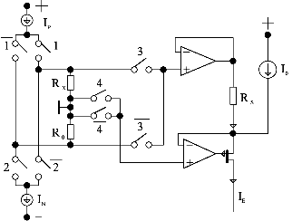
Figure 1 shows the circuit diagram of the voltage-to-current converter. The currents IP and IN convert the unknown resistance of RX and the resistance of R0 (which is used as reference) to a voltage. The input current (IE) of the ADC is the sum of an offset current (IO) and the current, which comes from the voltage across RX or R0 (depending on the pairs of switches 3 and 4) and RS. IO makes IE positive for all values of RX and both currents IN and IP.
Fig. 1: Voltage-to-current converter
The control signals for the switches 1 to 4 are provided by the microcomputer. For one value of RX we get four different currents IE and therefore also four results of an analog-to-digital conversion. From these results we can get the ratio RX/R0 by subtraction and division without errors of the order zero (thermo- and offset voltages) and the order one (value of IP, IN and R0).
Figure 2 shows the structure of the ADC [7], [10], [11]. The comparator S determines the discharge of capacitor Ci after the conversion. Comparator C is used to show that the voltage across Ci is lower than the voltage URef. Switch 9 is used to start the conversion with the capacitor Ci discharged. The complementary pair of switches 6 can guide the current IE either to the input or the output of the integrator. The same is done with the reference currents IR and IR/256 and the switches 7 and 8.
The current IE is integrated for 0.1 s. The reference current IR compensates IE in this phase using a Charge-Balance method. The charge in Ci after this integration is determined with the help of IR/256. The numeric result of this conversion is 256 times the number of clocks during the disintegration using IR in addition to the number of clocks used for discharging with IR/256.
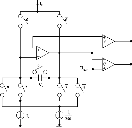
Fig. 2: Structure of the ADC
To control all the switches and to provide the time frame for the conversion a digital control unit is used. The number of clocks is counted by the microcomputer which also calculates the temperature either using IEC751 or ITS-90.
To be able to add more channels, to add more flexibility to the system of the thermometer and to overcome the electromagnetic compatibility (EMC) problems with digital signals on lines (between the comparators and the microcomputer) near a 23-bit ADC an ASIC (ENDEAVOR) was designed [12].
The number of channels was increased to eight. The counters for the clock pulses, which are the result of the analog-to-digital conversion, are added on-chip. There are no digital signals outside the ASIC when a conversion is made. On-chip counters have a low load capacitance on the clock line. Spikes in the power supply are therefore avoided. The information is serially transferred to the microcomputer at a time, when no conversion is going on. The digital signals then can cause no interference to the result of the conversion.
Figure 3 shows the block diagram of ENDEAVOR. A crystal oscillator provides the system clock of 1 MHz. Counters and decoders generate the control signals. A baudrate generator is implemented to provide a serial output signal of 9600 baud. The information has ASCII format, so a simple terminal program can be used to visualize the results of the conversions. The implementation of the original control unit guarantees compatibility to the existing system. The channels are periodically activated for measurement. The sequence can be set up with control signals.
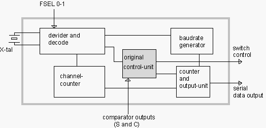
Fig. 3: Block diagram of the ASIC
The ASIC is in fabrication (0.8 µm AMS CMOS-process) at the moment. The transistor count is approximately 5500. The size is 1.9x1.9 mm2. A 28 pin PLCC package is used. The first engineering samples are expected for the middle of March 1997. Then it will be seen if the selected targets could be reached:
Conclusion
The use of ASICs in electronic instrumentation offers a wide spectrum of advantages. Topics which lead to the decision to start the design of an ASIC are not only reduction of space and power consumption but are also sometimes problems of EMC. In most cases the functionality and reliability of the system can be raised as shown with the examples of the industrial instrumentation (multi-channel measurements and better overall performance). BiCMOS technology is supposed to bring new advantages in some critical analog integrated circuits.
Acknowledgment
The "Steiermärkische Landesregierung, Abteilung für Wirtschaftsförderung" is funding this project by carrying a substantial part of the cost for personnel. Without this support a continuous activity in the area of ASIC-Design at the Department of Electronics would not be possible.
[1] H. Leopold, M. Pacher, R. Röhrer, G. Winkler: "Monolithische integrierte Steuerschaltung für A/D-Umsetzer", Arbeitsbericht der Informationstagung Mikroelektronik 1989, 386 – 391
[2] P. Söser: "Ein höchstauflösendes Sensorinterface für die Abbildungsgrößen Spannungsverhältnis und Zeit", Dissertation, Institut für Elektronik, TU Graz. Eigenverlag, 1993
[3] H. Leopold, R. Röhrer, P. Söser: "Monolithischer Quantisierer und Kodierer für als Periode und Tastverhältnis dargestellte analoge Größen", Tagungsbericht des Fortbildungsseminares der Gesellschaft für Mikroelektronik, Großarl 1993, 121 – 127
[4] Österreichisches Patent 380339, 1986
[5] H. Leopold, P. Söser, W. Steiner, G. Winkler: "Eine monolithische Steuerschaltung für Leistungs-H-Brücken", Arbeitsbericht der Informationstagung Mikroelektronik 1991, 15 – 20
[6] W. Meusburger, R. Röhrer, H. Senn, P. Söser: "ENDOR — Ein ASIC für ein batteriebetriebenes Handdichtemeßgerät", in print, Tagungsbericht AUSTROCHIP 97, 1997
[7] H. Leopold: "An den Grenzen der Genauigkeit elektronischer Analogschaltungen", Telematik 1. 1995, 8 – 12
[8] H. Leopold, K. Schröcker: "Ein eichfähiges Millikelvinthermometer für -200 °C bis +800 °C", Arbeitsbericht der Informationstagung Mikroelektronik 1987, 219 – 223
[9] H. Preston-Thomas H.: "The international Temperature Scale of 1990 (ITS-90)", Metrologia 27, 1990, 3 – 10
[10] K. Schröcker: "A/D-Wandler für das Millikelvin-Thermometer", presentation on 5 October 1987, Institut für Elektronik, TU Graz.
[11] H. Leopold, K. Schröcker, M. Holzer: "Verifikation der Genauigkeit einer Analogschaltung im PPM-Bereich", Arbeitsbericht der Informationstagung Mikroelektronik 1989, 392 – 396
[12] H. Leopold, W. Meusburger, J. Pfeiffer, H. Senn, G. Winkler: "ENDEAVOR — Ein ASIC für ein hochgenaues Thermometer", in print, Tagungsbericht AUSTROCHIP 97, 1997
Project Information
Project Manager
Dipl.-Ing. Dr. Peter Söser
Institut für Elektronik, TU Graz, Graz, Austria
Project Group
|
Last Name |
First Name |
Status |
Remarks |
|
Drexel |
Werner |
student |
Inst. f. Elektronik |
|
Leopold |
Hans |
university professor |
BMWFuK |
|
Meusburger |
Walter |
assistant |
BMWFuK |
|
Röhrer |
Robert |
assistant professor |
BMWFuK |
|
Schatzberger |
Gregor |
student |
Inst. f. Elektronik |
|
Senn |
Helmuth |
researcher |
Inst. f. Elektronik |
|
Söser |
Peter |
assistant |
BMWFuK |
The salaries for H. Senn, G. Schatzberger and W. Drexel were refunded by Steiermärkische Landesregierung, Abteilung für Wirtschaftsförderung.
Publications in Reviewed Journals
Presentations
Cooperations