Development of a 35 GHz Radar Sensor
A. Efanov, K. Lübke, Ch. Diskus, A. Springer, A. Stelzer, H.W. Thim
Institut für Mikroelektronik, Johannes Kepler Universität
A-4040 Linz, Austria
Experimental results with two different 35-GHz Doppler radar units are reported in this contribution. The system consists of a planar GaAs transferred electron oscillator and an InGaAs-mixer diode. The oscillator is a MESFET-like structure with a negatively biased Schottky-gate. A stationary high-field domain is formed underneath the gate and acts as a transit-time-independent broadband negative differential resistance. To achieve mixing with high sensitivity at zero bias the energy barrier of the diode must be made low. The mixer diode used in this module consists of 0.18 µm InGaAs with 38 % In content and 1× 1017 cm-3 Si n-type doping. This yields an energy barrier of 0.3 eV. With the first design a sensitivity of 1 mV/µW has been obtained.
Millimeter-wave radar sensor systems especially suited for automotive applications were intensively developed during the last few years [1], [2]. Combination of a low-cost technology together with advanced electrical characteristics and high reliability is a cornerstone requirement for an application in the automotive industry [3], [4]. Since the microwave front-end unit is the key unit determining the system’s performance and cost, it is the most crucial part of the whole system. Two different 35 GHz low-cost RF front-end Doppler units suited for automotive applications have been constructed. The homodyne unit consists of both receiving and transmitting corporate-fed microstrip patch array antennas, a microstrip directional coupler, a monolithic GaAs FECTED oscillator, and an integrated single Schottky diode mixer. The autodyne configuration uses only one antenna and the FECTED as a self-oscillating mixer. Inexpensive microstrip technology has been used, which yields a good compromise between cost factor and technical performance.
System Configuration
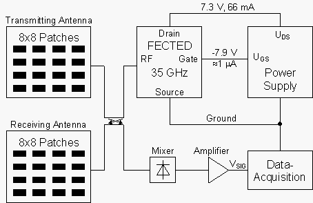
The block diagram of the front-end unit is shown in Fig. 1. The output power of the oscillator is fed into the transmitting antenna. At the mixer diode the reflected signal from the receiving antenna is combined with the LO signal provided by the 10 dB directional coupler. The amplified IF signal is fed into a signal processor. This configuration is suitable for both Doppler CW (continuous waveforms) as well as FM (frequency-modulated) CW radar systems.

Fig. 1: Block diagram of the front-end unit using homodyne detection.
Further cost and size reductions of the module have been obtained with a simplified system configuration as shown in Fig. 2. In this design the FECTED (field effect controlled transferred electron device)-oscillator acts as a self-oscillating mixer [5] thereby sparing the mixer diode as well as the directional coupler and the second antenna. In this mode of operation the reflected signal received from the antenna changes the effective load impedance of the oscillator resulting in changes of both oscillator power and frequency which can be detected as bias current variations. A bandpass amplifier is used to separate the small bias current variations from the large DC current.

Fig. 2: Block diagram of the simplified front-end using autodyne detection.
Antennas
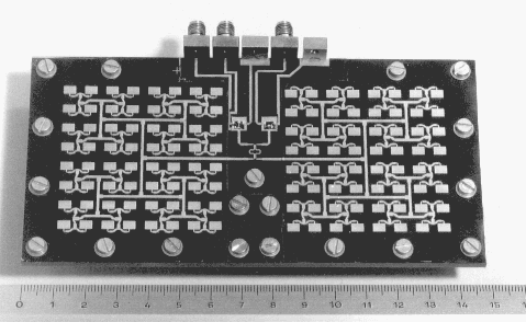
Two linearly-polarized corporate-fed microstrip patch array antennas have been designed for this system. The first one is a 4x4 array antenna with 16 degrees beamwidth and 17.5 dB (isotropic) power gain. The second one is a 8x8 array antenna with 8 degrees beamwidth and 21.5 dB (isotropic) power gain. The VSWR of both prototypes is below 2. A relatively inexpensive RT/duroid 5880 (a trademark of Rogers Corp.) substrate material of 0.254 mm thickness has been used for the fabrication of the antennas and the 10 dB directional coupler. The passive part has been made using standard photolithography and etching-technology, and has been covered by a gold film in order to minimize losses. A more detailed description of the antennas is given in [6]. Fig. 3 shows a photograph of the 8x8 array antenna module.

Fig. 3: Photograph of the front-end unit with 8x8 array antenna
Oscillator
In order to minimize costs a special planar Gunn diode has been used instead of a sophisticated transistor oscillator. This approach relaxes the demands on the resolution of the lithography. The device is called FECTED (Field Effect Controlled Transferred Electron Device) and is described elsewhere in this report. The device and the circuit have been fabricated on a 4x5 mm2 GaAs chip with standard processing technologies. With the FECTED oscillator mounted in the sensor front-end an output power of about 4 mW at 34 GHz with an efficiency of 0.8 % has been measured. Further details of the FECTED have been published in [7].
Mixer Diode
Voltage sensitivity
The voltage sensitivity of a detector diode is defined as the output voltage generated by the diode into the load circuit divided by the RF-power absorbed in the diode. The goal of the optimization procedure is to make this sensitivity as large as possible [8].
The voltage sensitivity, bv, of a circuit with load resistance RL is given by
 .
.
Is reverse saturation current
I0 bias current
Cj junction capacitance of the diode
Rs series resistance
Rj dynamic resistance (= q/nkT (Is+I0)).
It is necessary to minimize both the junction capacitance and the series resistance. The capacitance of the diode can be decreased if the size of the junction diameter is reduced. To obtain low series resistance the conductivity of the bulk material should be as high as possible, the current path through the material should be as short as possible and a good ohmic contact (low resistivity) is needed.
It is well known that large LO power is needed to minimize conversion loss of a GaAs Schottky mixer diode. This is a consequence of the high barrier height of about 0.7 eV of GaAs Schottky diodes. For a typical set of parameters for 10 µm x 10 µm Schottky barrier diodes (f = 35 GHz, n = 1.4, Rs = 10 W, Cj = 70 fF, RL = 1 MW) the maximum of the sensitivity bv can be calculated from the above equation. If the detector should be used without bias current, which simplifies circuitry, then I0 = 0 and the saturation current Is has to be in the range of 10-6 A. This corresponds to a barrier height of approximately 0.22 – 0.25 eV. However, the barrier height can be reduced if InxGa1-xAs is used. With increasing x the energy gap of the semiconductor is lowered from 1.42 eV (x = 0; i.e. GaAs) to 0.33 eV for x = 1 (InAs). With decreasing energy gap the barrier height of the Schottky contact is also reduced. With In0.38Ga0.62As the desired barrier height can be adjusted.
Diode fabrication
The diodes have been fabricated using epitaxial layers of In0.38Ga0.62As grown by metal organic vapor deposition (MOCVD) on semi-insulating GaAs substrates. In order to grow good quality In0.38Ga0.62As layers on GaAs a graded buffer layer is needed to compensate the difference in lattice constants between InGaAs and GaAs. The Indium content is increased from 0 to 38% in steps of 5% in this layer. The first active layer grown is an n+-layer doped 6·1018 cm-3 with a thickness of 0.8 µm. On top of this layer a 0.19 µm thick n-layer with 2·1016 cm-3 doping concentration has been grown. The ohmic contact is recessed to the n+-layer and the connection to the Schottky-contact on the top is led over a SiO2-bridge.

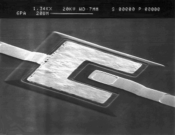
Fig. 4: SEM picture of the InGaAs Schottky diode
In Fig. 4, a SEM picture of the diode is shown. With the first design a sensitivity of 1 mV/µW has been obtained.
Results
Both front-end units have been tested with a target moving at a constant speed of 0.37 m/s from a distance of 2 meters towards the antenna. In the case of homodyne detection the amplified mixer signal VSIG shown in Fig. 5 corresponds almost perfectly to the theoretic Doppler signal which is a harmonic function for constant target velocity. With a triangular corner reflector at a distance of 22 m, a signal amplitude of 100 mV after an amplification by a factor of 305 has been measured.
For the autodyne configuration the detection range is much shorter because the reflected power received by the antenna must be sufficient to modulate the oscillator’s output power. This modulation is highly nonlinear but periodical with half the wavelength as can be seen in Fig. 6 where the drain current modulation measured at a shunt and amplified is displayed.
Conclusion
Two different inexpensive configurations of the microwave part of a 35-GHz Doppler radar sensor system have been presented. The described approaches make it possible to achieve acceptable system performance with low-cost technology. The front-end with two antennas and the mixer diode has an operational range of at least 25 m. It is expected that this distance can be enhanced by optimizing the system components without increasing the transmitted power. A further cost reduction can be achieved by monolithically integrating the system on a single chip. The autodyne configuration has less sensitivity and higher noise level but it is the simplest and therefore cheapest approach.
Acknowledgments
The authors would like to thank G. Hinterberger, G. Hofmann and J. Katzenmayer for fabricating and testing the devices. This work was supported by the Austrian Science Foundation (FWF) under Contract number P8697-TEC.
References
[1] H.H. Meinel: "Commercial Applications of Millimeterwaves History, Present Status and Future Trends", IEEE Trans. on Microwave Theory and Techniques, (1995) 43, n° 7, pp. 1639 – 19.
[2] K.W. Chang, H. Wang, G. Shreve, J.G. Harrison, M. Core, A. Paxton, M. Yu, C.H. Chen, and G.S. Dow: "Forward-Looking Automotive Radar Using a W-band Single-Chip Transceiver", IEEE Trans. on Microwave Theory and Techniques, (1995) 43, n° 7, pp. 1659 – 1668.
[3] P. Heide, R. Schubert, V. Mágori, and R. Schwarte: "Coded 24 GHz Doppler Radar Sensors: A New Approach to High-Precision Vehicle Position and Ground-Speed Sensing in Railway and Automobile Applications", IEEE MTT-S Digest, International Microwave Symposium, Orlando, (1995), n°2, WE4D-4, pp. 965 – 968.
[4] J.-F. Luy, K.M. Strohm, H.-E. Sasse, A. Schüppen, J. Buechler, M. Wollitzer, A. Gruhle, F.Schäffler, U. Guettich, and A. Klaaßen: "Si/SiGe MMIC’s", IEEE Trans. on Microwave Theory and Techniques, (1995) 43, n° 4, pp. 705 – 714.
[5] P.A. Jefford and M. J. Howes: "Modulation Schemes in Low-Cost Microwave Field Sensors", IEEE Trans. on Microwave Theory and Techniques, (1983) 31, n° 8, pp. 613 – 624.
[6] A. Efanov and H.W. Thim: "Corporate-Fed 2x2 Planar Microstrip Patch Sub-Array for the 35 GHz Band", Antennas and Propagation Magazine, (1995) 37, n° 5, pp. 49 – 51.
[7] K. Lübke, H.Scheiber, and H. Thim: "A Voltage Tunable 35 GHz Monolithic GaAs FECTED oscillator", IEEE Microwave and Guided Wave Letters, (1991) 1, n°2, pp. 35 – 37.
[8] I. Bahl, P. Bartia: Microwave Solid State Curcuit Design, Wiley, New York 1988.
Project Information
Project Manager
Univ. Prof. Dr. Hartwig Thim
Institut für Mikroelektronik, Kepler-Universität Linz, A-4040 Linz
Project Group
|
Last Name |
First Name |
Status |
Remarks |
|
Diskus |
Christian |
postdoc |
|
|
Efanov |
Andrew |
postdoc |
Aerospace Monitoring Center, Lvov, Ukraine |
|
Hilgarth |
Thomas |
student |
|
|
Hinterberger |
Gabriele |
technician |
|
|
Hofmann |
Gerald |
technician |
|
|
Katzenmayer |
Hans |
technician |
|
|
Lübke |
Kurt |
postdoc |
|
|
Springer |
Andreas |
dissertation |
|
|
Thim |
Hartwig |
university professor |
Books and Contributions to Books
Publications in Reviewed Journals
Doctor’s Theses
Cooperations